How much do you know about light switches? Jupiterimages / Getty Images
When you're furnishing a home, light is everything. The light level in a room dictates what you can and can't do, and it has a huge effect on how you feel. You can't read very easily by a single candle, for example, and a romantic dinner for two isn't so romantic under a 1,500-watt halogen lamp.
The problem is that people need to use some rooms for multiple purposes, and these different functions call for varying amounts of light. Enter the dimmer switch, a handy electrical component that lets you adjust light levels from nearly dark to fully lit by simply turning a knob or sliding a lever.
Advertisement
In this article, we'll look inside one of these everyday devices to find out how it controls lamp fixtures. As it turns out, the inner workings are pretty cool -- and surprising. Modern dimmer switches work in a totally unexpected way.
Early dimmer switches had a pretty straightforward solution to adjusting light levels -- a variable resistor. An ordinary resistor is a piece of material that doesn't conduct electrical current well -- it offers a lot of resistance to moving electrical charge. A variable resistor consists of a piece of resistive material, a stationary contact arm and a moving contact arm.
As the charge works to move through the resistor, energy is lost in the form of heat. When you put a resistor in a series circuit, the resistor's energy consumption causes a voltage drop in the circuit, decreasing the energy available to other loads (the light bulb, for example). Decreased voltage across the light bulb reduces its light output.
Advertisement
The problem with this solution is that you end up using a lot of energy to heat the resistor, which doesn't help you light up the room but still costs you. In addition to be being inefficient, these switches tend to be cumbersome and potentially dangerous, since the variable resistor releases a substantial amount of heat.
Modern dimmer switches take a more efficient approach, as we'll see in the next section.
The New and Improved Way
Instead of diverting energy from the light bulb into a resistor, modern resistors rapidly shut the light circuit off and on to reduce the total amount of energy flowing through the circuit. The light bulb circuit is switched off many times every second.
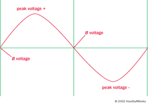
The switching cycle is built around the fluctuation of household alternating current (AC). AC current has varying voltage polarity -- in an undulating sine wave, it fluctuates from a positive voltage to a negative voltage. To put it another way, the moving charge that makes up AC current is constantly changing direction. In the United States, it goes through one cycle (moving one way, then the other) 60 times a second. The diagram below shows this sixtieth-of-a-second cycle.
Advertisement
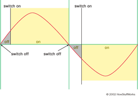
A modern dimmer switch "chops up" the sine wave. It automatically shuts the light bulb circuit off every time the current reverses direction -- that is, whenever there is zero voltage running through the circuit. This happens twice per cycle, or 120 times a second. It turns the light circuit back on when the voltage climbs back up to a certain level.
This "turn-on value" is based on the position of the dimmer switch's knob or slider. If the dimmer is turned to a brighter setting, it will switch on very quickly after cutting off. The circuit is turned on for most of the cycle, so it supplies more energy per second to the light bulb. If the dimmer is set for lower light, it will wait until later in the cycle to turn back on.
That's the basic concept, but how does the dimmer actually do all of this? In the next couple of sections, we'll look at the simple circuitry that makes it work.
The Triac
In the last section, we saw that a dimmer switch rapidly turns a light circuit on and off to reduce the energy flowing to a light switch. The central element in this switching circuit is a triode alternating current switch, or triac.
A triac is a small semiconductor device, similar to a diode or transistor. Like a transistor, a triac is made up of different layers of semiconductor material. This includes N-type material, which has many free electrons, and P-type material, which has many "holes" where free electrons can go. For an explanation of these materials, check out How Semiconductors Work. And, for a demonstration of how these materials work in a simple transistor, see How Amplifiers Work.
Advertisement
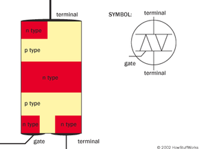
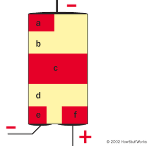
Here's how the N-type and P-type material is arranged in a triac.
You can see that the triac has two terminals, which are wired into two ends of the circuit. There is always a voltage difference between the two terminals, but it changes with the fluctuation of the alternating current. That is, when current moves one way, the top terminal is positively charged while the bottom terminal is negatively charged, and when the current moves the other way the top terminal is negatively charged while the bottom terminal is positively charged.
The gate is also wired into the circuit, by way of a variable resistor. This variable resistor works the same basic way as the variable resistor in the old dimmer switch design, but it doesn't waste nearly as much energy generating heat. You can see how the variable resistor fits into the circuit in the diagram below.
So what's going here? In a nutshell:
The triac acts as a voltage-driven switch.
The voltage on the gate controls the switching action.
The variable resistor controls the voltage on the gate.
In the next section, we'll look at this process in greater detail.
The Circuit
When there is "normal" voltage across the terminals and little voltage on the gate, the triac will act as an open switch -- it won't conduct electricity. This is because the electrons from the N-type material fill in holes along the border with the P-type material, creating depletion zones, insulated areas where there are few free electrons or holes (see this page for a full explanation of depletion zones).
If you apply a strong enough voltage to the gate, it will disrupt the depletion zones so electrons can move across the triac. The exact sequence varies depending on the direction of the current -- that is, which part of the AC cycle you're in. Let's say the current is flowing so the top terminal is negatively charged and bottom terminal is positively charged. The circuit is arranged so that the voltage boost on the gate will have the same charge as the top terminal. So we get something that looks like this:
Advertisement
When the gate is "charged," the voltage difference between the gate and the lower terminal is strong enough to get electrons moving between them. Moving electrons out of the N-type material -- area e -- disrupts the depletion zone between areas e and d. Introducing more free electrons into area d disrupts the depletion zone between d and c. Electrons from area c can move toward the bottom terminal, jumping from hole to hole in area d. This introduces more holes into area c, which gets electrons moving out of the depletion zone between c and b. The voltage is strong enough to drive electrons from area a into the holes in area b, disrupting the last depletion zone. With the depletion zones dispersed, electrons can move freely from the top terminal to the bottom terminal -- the triac is now conductive! (Note: Some dimmer switches also contain a similar semiconductor device called a diac, in addition to a triac. These circuits work in the same basic way.)
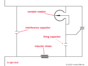
In order for the triac to start conducting electricity between its two terminals, it needs a voltage boost on its gate. The required voltage level doesn't change, but you can adjust how long it takes the gate to "charge up" to this voltage. This is where the variable resistor and the firing capacitor come in.
Current passes through the variable resistor and charges the firing capacitor (current builds up electrical charge on the capacitor's plates -- see How Capacitors Work for more information). When the capacitor builds up a certain amount of charge, it has the necessary voltage to conduct current from the gate to the bottom terminal. It discharges, making the triac conductive.
Turning the dimmer switch knob pivots the contact arm (or contact plate) on the variable resistor, increasing or decreasing its total resistance. When the knob is set to "dim," the variable resistor offers greater resistance so it "holds up" the current. As a result, the necessary boost voltage doesn't build up as quickly on the firing capacitor. By the time the capacitor is charged enough to make the triac conductive, the AC current cycle is well underway. If you turn the knob the other way, the variable resistor offers less resistance and the capacitor gets up to the necessary boost voltage earlier in the fluctuating cycle.
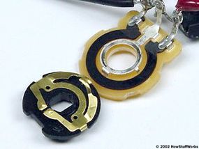
The variable resistor from a basic dimmer switch
As soon as the current fluctuates back to the zero voltage point, there is nothing driving current through the triac, so the electrons stop moving. The depletion zones form again, and the triac loses its conductivity until the boost voltage builds up on the gate.
This system works very well, but it does create an odd problem: It tends to produce a distinctive buzzing in the light bulb. In the next section, we'll find out why this is.
Dimmer Buzzing
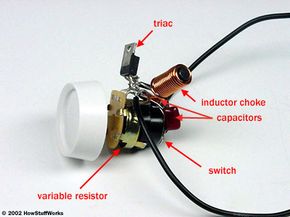
The guts of a basic dimmer switch
If you hook up a really cheap dimmer switch, you may notice a strange buzzing noise. This comes from vibrations in the bulb filament caused by the chopped-up current coming from the triac.
If you've read How Electromagnets Work, you know that electricity flowing through a coiled length of wire generates a substantial magnetic field, and fluctuating current generates a fluctuating magnetic field. If you've read How Light Bulbs Work, you know that the filament at the heart of a light bulb is just a coiled length of wire. It makes sense, then, that this coiled filament becomes magnetic whenever you pass current through it, and the magnetic field fluctuates with the AC current.
Advertisement
Normal undulating AC current fluctuates gradually, so the magnetic field does, too. The chopped-up current from a dimmer switch, on the other hand, jumps in voltage suddenly whenever the triac becomes conductive. This sudden shift in voltage changes the magnetic field abruptly, which can cause the filament to vibrate -- it's rapidly drawn to and repelled by the metal arms holding it in place. In addition to producing a soft buzzing sound, the abruptly shifting magnetic field will generate weak radio signals that can cause interference on nearby TVs or radios!
Better dimmer switches have extra components to squelch the buzzing effect. Typically, the dimmer circuit includes an inductor choke, a length of wire wrapped around an iron core, and an additional interference capacitor. Both devices can temporarily store electrical charge and release it later. This "extra current" works to smooth out the sharp voltage jumps caused by the triac-switching to reduce buzzing and radio interference. (See How Inductors Work and How Capacitors Work for more information.)
Some high-end dimmer switches, such as the ones commonly used in stage lighting, are built around an autotransformer instead of a triac. The autotransformer dims the lights by stepping down the voltage flowing to the light circuit. A movable tap on the autotransformer adjusts the step-down action to dim the lights to different levels. Since it doesn't chop up the AC current, this method doesn't cause the same buzzing as a triac switch.
There are a lot of other dimmer switch varieties out there, including touchpad dimmers and photoelectric dimmers, which monitor the total light level in a room and adjust the dimmer accordingly. Most of these are built around the same simple idea -- chopping up AC current to reduce the total energy powering a light bulb. At the most basic level, that's all there is to it.
For more information on dimmer switches, including an installation guide, check out the links on the next page.