The Circuit
When there is "normal" voltage across the terminals and little voltage on the gate, the triac will act as an open switch -- it won't conduct electricity. This is because the electrons from the N-type material fill in holes along the border with the P-type material, creating depletion zones, insulated areas where there are few free electrons or holes (see this page for a full explanation of depletion zones).
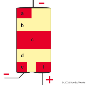
If you apply a strong enough voltage to the gate, it will disrupt the depletion zones so electrons can move across the triac. The exact sequence varies depending on the direction of the current -- that is, which part of the AC cycle you're in. Let's say the current is flowing so the top terminal is negatively charged and bottom terminal is positively charged. The circuit is arranged so that the voltage boost on the gate will have the same charge as the top terminal. So we get something that looks like this:
Advertisement
When the gate is "charged," the voltage difference between the gate and the lower terminal is strong enough to get electrons moving between them. Moving electrons out of the N-type material -- area e -- disrupts the depletion zone between areas e and d. Introducing more free electrons into area d disrupts the depletion zone between d and c. Electrons from area c can move toward the bottom terminal, jumping from hole to hole in area d. This introduces more holes into area c, which gets electrons moving out of the depletion zone between c and b. The voltage is strong enough to drive electrons from area a into the holes in area b, disrupting the last depletion zone. With the depletion zones dispersed, electrons can move freely from the top terminal to the bottom terminal -- the triac is now conductive! (Note: Some dimmer switches also contain a similar semiconductor device called a diac, in addition to a triac. These circuits work in the same basic way.)
In order for the triac to start conducting electricity between its two terminals, it needs a voltage boost on its gate. The required voltage level doesn't change, but you can adjust how long it takes the gate to "charge up" to this voltage. This is where the variable resistor and the firing capacitor come in.
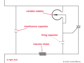
Current passes through the variable resistor and charges the firing capacitor (current builds up electrical charge on the capacitor's plates -- see How Capacitors Work for more information). When the capacitor builds up a certain amount of charge, it has the necessary voltage to conduct current from the gate to the bottom terminal. It discharges, making the triac conductive.
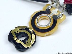
Turning the dimmer switch knob pivots the contact arm (or contact plate) on the variable resistor, increasing or decreasing its total resistance. When the knob is set to "dim," the variable resistor offers greater resistance so it "holds up" the current. As a result, the necessary boost voltage doesn't build up as quickly on the firing capacitor. By the time the capacitor is charged enough to make the triac conductive, the AC current cycle is well underway. If you turn the knob the other way, the variable resistor offers less resistance and the capacitor gets up to the necessary boost voltage earlier in the fluctuating cycle.
As soon as the current fluctuates back to the zero voltage point, there is nothing driving current through the triac, so the electrons stop moving. The depletion zones form again, and the triac loses its conductivity until the boost voltage builds up on the gate.
This system works very well, but it does create an odd problem: It tends to produce a distinctive buzzing in the light bulb. In the next section, we'll find out why this is.